BLE Interface
In the BLE API design, the DWM module acts as the BLE peripheral and can be communicated by BLE central devices through the APIs. This document introduces the APIs that the BLE central devices can use for the communication. An Android application and PANS PRO Manager are provided to exercise the BLE APIs.
The BLE central device directly connects with the network nodes to set up and retrieve parameters. It needs to connect to each device individually to configure/control.
In the BLE scheme, normal GATT operations, including read, write, and notification are provided.
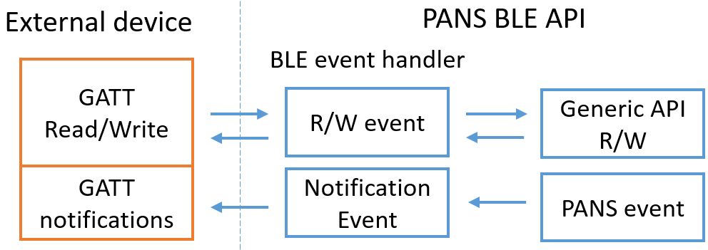
The figure above show that’s the DWM1001 BLE event handler translates the GATT operations into generic API commands. In the meantime, when there are BLE-related events, the BLE event handler will send the corresponding notification to the BLE client.
Detailed BLE APIs are introduced in section BLE API.
LE GATT Model
The network node service UUID is 680c21d9-c946-4c1f-9c11-baa1c21329e7. All characteristic values are encoded as little endian as BLE specification suggests.
Network Node Characteristics
uuid |
name |
Length |
Value |
flags |
|---|---|---|---|---|
“Std. GAP service, label 0x2A00” |
Label |
Var |
UTF-8 encoded string |
RW |
3f0afd88-7770-46b0-b5e7-9fc099598964 |
Operation mode |
2 bytes |
See the section below for details on data encoding |
RW |
80f9d8bc-3bff-45bb-a181-2d6a37991208 |
Network ID |
2 bytes |
Unique identification of the network (PAN ID) |
RW |
a02b947e-df97-4516-996a-1882521e0ead |
Location data mode |
1 byte |
0 - Position 1 - Distances 2 - Position + distances” |
RW |
003bbdf2-c634-4b3d-ab56-7ec889b89a37 |
Location data |
106 bytes max |
See the section below for details on data encoding |
RO |
f4a67d7d-379d-4183-9c03-4b6ea5103291 |
Proxy positions |
76 bytes max |
Used by the module as a notification about new tag positions for the BLE central |
RO |
1e63b1eb-d4ed-444e-af54-c1e965192501 |
Device info |
29 bytes |
Node ID (8 bytes), HW version (4 bytes), FW1 version (4 bytes), FW2 version (4 bytes), FW1 checksum (4 bytes), FW2 checksum (4 bytes), RDonly Operation flags (1 byte) |
RO |
1e630001-d4ed-444e-af54-c1e965192501 [PANS PRO] |
Device status |
8 bytes |
Uptime (4 bytes, unsigned integer), battery level (1 byte, unsigned integer), reserved (1 byte) , temperature (2 bytes, integer) |
RO |
0eb2bc59-baf1-4c1c-8535-8a0204c69de5 |
Statistics |
120 bytes |
Node statistics |
RO |
5955aa10-e085-4030-8aa6-bdfac89ac32b |
FW update push |
Max 37 bytes |
Used to send structured data (FW update packets) to the module (BLE peripheral), the size is set according to max transmission unit (MTU). See the section below for details on data encoding. |
WO |
9eed0e27-09c0-4d1c-bd92-7c441daba850 |
FW update poll |
9 bytes |
Used by the module as a response/notification for the BLE central. See the section below for details on data encoding. |
RO |
ed83b848-da03-4a0a-a2dc-8b401080e473 |
Disconnect |
1 byte |
Used to explicitly disconnect from BLE peripheral by writing value=1 (workaround due to Android behavior) |
WO |
“5b10c428-af2f-486f-aee1-9dbd79b6bccb [PANS PRO Modified]” |
Anchor list |
65 bytes |
Count (1 byte), list of node IDs (2 bytes), RSSI (1 byte), seat (1 bytes) max 16 elements in list |
RO |
9d5ab03b-cbf8-4ae5-9f11-63e45f538ada |
AES key |
16 bytes |
AES symmetric key To be implemented in R2 |
RW |
Note
The label characteristic is a special one. It is part of the standard mandatory GAP service (0x1800) under the standard Name characteristic (0x2A00).
Operation mode characteristic
The operation mode characteristic is of 2 bytes and contains the configuration information of the nodes. The format is defined as follows:
1st byte (bit 7 down to 0) |
|
|---|---|
Bit |
Value |
7 |
tag (0), anchor (#. |
6 - 5 |
UWB - off (0), passive (#., active (2) |
4 |
firmware 1 (0), firmware 2 (#. |
3 |
accelerometer enable (0, #. |
2 |
LED indication enabled (0, #. |
1 |
firmware update enable (0, #. |
0 |
BLE enabled (0,#. |
2nd byte (bit 7 down to 0) |
|
|---|---|
Bit |
Value |
7 |
initiator enable, anchor specific (0, #. |
6 |
low-power mode enable, tag specific (0, #. |
5 |
location engine enable, tag specific (0, #. |
4 - 0 |
reserved |
Location data characteristic
Location data characteristics can contain position, distances or both. The format of the position and distances are defined as follows:
Type (1 byte) |
Value |
|---|---|
0 - Position only |
X,Y,Z coordinates (each 4 bytes)+ quality factor (1 byte), size: 13 bytes |
1 - Distances |
The first byte is distance count (1 byte). Sequence of node ID (2 bytes), distance (4 bytes), and quality factor (1 byte). Max value contains 15 elements, size: 8 - 106. |
2 - Position and Distances |
Encoded Position (as described above, 13 bytes) Encoded Distances (as described above, 8 - 29 bytes) - position and distances are sent by tag, number of ranging anchors is max 4. |
Note
The characteristic value might be completely empty (zero length), meaning that there are neither known positions nor known distances.
Note
Although location data mode includes position and distances, it is still possible to receive distances only in the characteristic in case a position is unknown.
Proxy Positions Characteristic
This characteristic is provided to overcome the limitations of concurrently connected nodes to the BLE central (mobile device). A passive node uses this characteristic to stream/notify about tag position updates.
Data are encoded in this characteristic as follows:
1 byte: number of elements (max 5)
[Sequence] tag position: 2 byte node ID, 13 byte position
Thus, the maximum size of 5 tag positions is 76 bytes long.
Anchor-specific Characteristics
An anchor may operate in a special mode called ‘Bridge’ and ‘Initiator’. These are orthogonal and do not influence each other. Bridge flag is read-only, while the user can set the initiator. Also, each anchor has a seat number within its cluster.
UUID |
Name |
Length |
Value |
Flags |
|---|---|---|---|---|
3f0af d88-7770-46 b0-b5 e7-9fc09959 8964 |
Operation Mode (see above) |
2 bytes |
Bit 7 in 2nd byte: initiator enable (0, #. (see subsection Operation Mode cha racteristic for detail), |
RW |
1e63 b1eb-d4ed-4 44e-a f54-c1e9651 92501 |
Device info (see above) |
RD only operation flags: BXXXXXXX B: bridge 1/0 |
RO |
|
f0f26c 9b-2c8c-49a c-ab6 0-fe03def1b 40c |
|
13 bytes |
coordinates each 4-byte precision + quality factor (1 byte, Value 1 - 100) |
WO |
28d0 1d60-89de-4 bfa-b 6e9-651ba59 6232c |
MAC stats |
4 bytes |
Reserved for internal debug MAC statistics |
RO |
17b16 13e-98f2-44 36-bc de-23af17a1 0c72 |
Cluster info |
5 bytes |
Seat number (1 by te)/Cluster map (2 byt es)/Cluster neighbor map (2 bytes) |
RO |
5b10c4 28-af2f-486 f-aee 1-9dbd79b6b ccb [Not in PANS PRO] |
Anchor list |
65 bytes |
Count (1 byte), list of node IDs (2 bytes), RSSI (1 byte), seat (1 bytes) max 16 elements in list [No longer available in PANS PRO as it is no longer ancho r-specific] |
RO |
Tag-specific Characteristics
Each tag determines its position based on the information sent by 4 surrounding anchors. The tag provides complete information on how its position is computed (read-only).
UUID |
Name |
Length |
Value |
Flags |
|---|---|---|---|---|
3f0a fd88-7770-4 6b0- b5e7-9fc099 598964 |
Operation Mode (see above) |
2 bytes |
Bit 6 in 2nd byte: low power mode enable (0, #. Bit 5 in 2nd byte: location engine enable (0, #. (see subsection Operation Mode cha racteristic for detail) |
RW |
7bd4 7f30-5602-4 389 -b069-83057 31308b6 |
Update rate |
8 bytes |
Layout: U1 (4 bytes), U2 (4 bytes) Broadcast new position each U1 ms when moving, broadcast new position each U2 ms when stationary. |
RW |
BLE Auto-Positioning
The BLE API also makes it possible to initiate an auto-positioning process. The auto-positioning process is finished (positions are computed) on the mobile device. The BLE API makes it possible to initiate distance measurement and retrieval. The workflow is as follows:
Measure:
Initiator is found and verified (the node must be a real initiator, not just configured as initiator).
Initiator/network is put to measure distances mode:
Make sure that location data mode is configured for distances or position and distances.
Start observing location data characteristics (setup cccd notification).
Receive all measured distances from the initiator and save the measured distances to the matrix.
Stop observation.
Distances from all other (non-initiator) nodes are retrieved:
Connect.
Make sure that location data mode is configured for distances or position and distances.
Retrieve the value stored in location data characteristic (directly) and save the measured distances to the matrix
Disconnect.
Evaluate: evaluate the measure distances, check orthogonality, and compute positions.
Save the computed positions to nodes (on user request).
BLE Advertisements
BLE advertisement is a common way for a peripheral device to let others know its presence. According to BLE spec, The broadcast payload is made of triplets, i.e. [length, type, <data>]. Anchors and tags will broadcast basic information about their presence and operation mode. The BLE advertisement is not long enough to also include the position info.
In the BLE advertisement, 31 bytes are used:
3 bytes are mandatory flags (one AD triplet).
The app can use the remaining 28 bytes to fill in AD records (each record has 2 bytes length+type overhead).
Presence Broadcast
The BLE on the DWM module works in connectable undirected mode. It advertises the presence broadcast that contains the availability of service and some service data. The presence broadcast follows the BLE advertisement frame structure and makes use of the 28 bytes to present information.
Since the presence is a broadcast with a connectable flag set to true, a shortened local name AD record of 8 bytes must be included here to overcome potential Android BLE stack bugs (as described in [1]). The remaining bytes are filled with service data: 2 bytes for the AD record header, 16 bytes UUID, 1 byte shortened operation mode and 1-byte change counter.
The presence broadcast frame has 3 + 20 + 8 bytes in total, i.e. 31 bytes (out of 31 bytes).The frame structure is shown in the table below.
AD triplet - part identification |
Value |
|---|---|
LEN |
0x02 |
TYPE |
0x01 (Flags) |
VALUE |
Device/Advertisement flags - connectable |
LEN |
0x13 (19 in decimal) |
TYPE |
0x21 (SERVICE_DAT). |
VALUE |
|
Bit layout: OXXEFFUU (1 byte) O - operation mode (tag 0, anchor #. XX - reserved E - error indication FF - flags: initiator, bridge UU - UWB: off (0), passive (#., active (2) |
|
Change counter (1 byte) - change counter changes each time a characteristic gets changed (except for node statistics and specifically for Tag: location dat#.. |
|
LEN |
0x07 (max) |
TYPE |
0x08 (Shortened local name) |
VALUE |
First 6 letters (or less) of device local name as defined by GATT spec. |
BLE Firmware Update
Firmware update functionality is used to update the module’s firmware. It can be performed either over UWB or BLE. This section describes the control and data flow over BLE.
During the FW update, two characteristics, FW update push and FW update poll are used to implement the request/response protocol.
Initiating FW Update
Steps:
The Mobile device (BLE central) sets up an indication on FW update poll characteristic changes (CCCD).
The Mobile device asks the network node if it is willing to perform the update by sending the update request/offer packet to FW update push characteristic. This initialization packet contains the firmware version, checksum, and overall firmware binary size (in bytes). This process is reliable write, also known as write with response.
The Network node responds with indication on the FW update poll in two cases:
Case 1: YES, “send me the first data buffer”. see Transmitting the FW binary section for more information;
Case 2: NO, and error code provides a refuse reason.
Error states:
Mobile device: Received explicit NO indication along with error code/reason. Resolution: The Mobile device disables CCCD indication on the FW update poll and notifies the upper layer about the refused reason. Network node: Sudden disconnect Resolution: Leave the FW update mode and reset the current state as if the FW update did not happen. Mobile device: Detects that connection has been closed. Resolution: Retry. If still unsuccessful after 30 seconds from FW update initialization, report to the upper layer. Let the user re-initiate the firmware update on request.
Transmitting the FW binary
This section is inspired by [2].
The network Node initiates the data transmission and tells the mobile device precisely which data buffer it requires. This communication is done using a FW buffer request: size and offset. Mobile device starts sending the requested buffer in small chunks using the write command without response and as such, there is no full round trip involved. The elementary chunk size equals to MTU to fit into a single transmitted packet. The chunk consists of:
Data: size should be rounded to a power of 2. The current chunk size is set to 32 bytes.
Relative offset (from the very beginning): 4 bytes.
Identification of the message type: FIRMWARE_DATA_CHUNK (= 0x1): 1 byte
The network node completely drives the data transmission . After the data buffer is sent, the mobile device waits for further instructions. During the transmission, the network node normally asks for data buffers sequentially, one by one, to get a continuous byte sequence of firmware. For instance, the node might ask for an unexpected buffer if there are exceptions, especially in cases where the current buffer transmission fails.
Error states:
Network node: data chunks are missing upon receiving (non-continuous sequence), or out-of-order chunks. Resolution: send FW buffer request specifying the missing chunk and the rest of the buffer. Mobile device: receives FW buffer request during ongoing data transmission. Resolution: stop sending data, set the current offset to the one in the FW buffer request and restart data transmission.
Finishing the transmission
Once the last data buffer has been successfully received, the network node will inform the mobile device through an indication on the FW update poll that it has received the full firmware binary.
Upon its reception, the mobile device:
Disconnects from the network node.
Waits 500 ms.
Tries to connect to the network node again and check its firmware status.
FW update push/poll format
FW update push |
|||||
|---|---|---|---|---|---|
Update offer/request- Firmware meta |
Type == 0 (1 byte) |
HW version (4 bytes) |
FW version (4 bytes) |
FW checksum (4 bytes) |
size (4 bytes) |
Firmware data chunk |
type == 1 (1 byte) |
offset (4 bytes) |
data (max 32 bytes) |
||
FW update poll |
|||
|---|---|---|---|
Firmware buffer request |
type == 1 (1 byte) |
offset (4 bytes) |
size (4 bytes) |
Signals |
type == 0 (upload refused), 2 (upload complete), 3 (save failed) 14 (save failed, invalid checksum) (1 byte) |
0 bytes |
|