DWM3001C
Note
To get more information, please visit the Qorvo’s DWM3001C page.
Key Features
IEEE 802.15.4-2015 and IEEE 802.15.4z BPRF compliant
Fully aligned with FiRa™ PHY, MAC and certification development
Supports Channels 5 (6.5 GHz) and 9 (8 GHz)
FCC, SRRC and ETSI certification (planned)
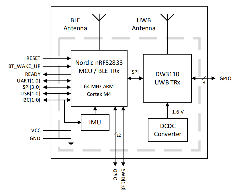
Nordic nRF52833 SoC with BLE transceiver
Supply voltage VCC: 2.5 V - 3.6 V
Bluetooth chip antenna
AES 128/256 Security block
Fully coherent receiver for maximum range and accuracy
Power consumption optimized for battery applications
Data rates of 850 kbps, 6.8 Mbps
Maximum packet length of 1023 bytes for high data throughput applications
Integrated MAC support features
Backward compatible with the DWM1001C module
Temperature range -40°C to +85°C
Software Compatibility
It is compatible with both LEAPS RTLS and PANS PRO RTLS.
Block Diagram
Pinouts Description
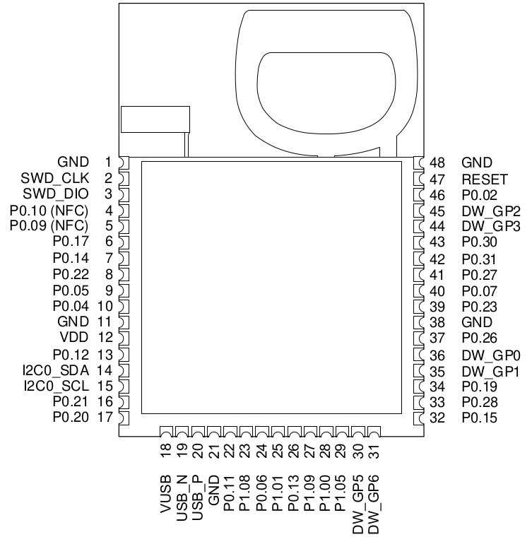
Pin Numbering
DWM3001C module pin assignments are as follows (viewed from top):
Pin Descriptions
Signal Name |
Pin |
I/O (Default) |
Description |
IC Pin Reference |
|---|---|---|---|---|
Digital Interface |
||||
SWD_CLK |
2 |
DI |
Serial wire debug clock input for debug and programming of nRF52833 processor. |
[N] SWDCLK |
SWD_DIO |
3 |
DIO |
Serial wire debug I/O for debug and programming of nRF52833 processor. |
[N] SWDIO |
P0.10 (NFC2) |
4 |
Mixed |
General purpose I/O for nRF52833 processor. NFC antenna connection. |
[N] P0.10 |
P0.09 (NFC1) |
5 |
Mixed |
General purpose I/O for nRF52833 processor. NFC antenna connection. |
[N] P0.09 |
P0.17 |
6 |
DIO |
General purpose I/O for nRF52833 processor. |
[N] P0.17 |
P0.14 |
7 |
DIO |
General purpose I/O for nRF52833 processor. |
[N] P0.14 |
P0.22 |
8 |
DIO |
General purpose I/O for nRF52833 processor. |
[N] P0.22 |
P0.05 |
9 |
DIO |
General purpose I/O for nRF52833 processor. |
[N] P0.05 |
P0.04 |
10 |
DIO |
General purpose I/O for nRF52833 processor. |
[N] P0.04 |
P0.12 |
13 |
DIO |
General purpose I/O for nRF52833 processor. |
[N] P0.12 |
I2C0_SDA |
14 |
DIO |
I2C data signal of nRF52833 processor and LIS12DH accelerometer. |
[N] P0.24 |
I2C0_SCL |
15 |
DIO |
I2C clock signal of nRF52833 processor sand LIS12DH accelerometer. |
[N] P1.04 |
P0.21 |
16 |
DIO |
General purpose I/O for nRF52833 processor. |
[N] P0.21 |
P0.20 |
17 |
DIO |
General purpose I/O for nRF52833 processor. |
[N] P0.20 |
USB_N |
19 |
DIO |
USB D- I/O for nRF52833 processor. |
[N] D- |
USB_P |
20 |
DIO |
USB D+ I/O for nRF52833 processor. |
[N] D+ |
P0.11 |
22 |
DIO |
General purpose I/O for nRF52833 processor. |
[N] P0.11 |
P1.08 |
23 |
DIO |
General purpose I/O for nRF52833 processor. |
[N] P1.08 |
P0.06 |
24 |
DIO |
General purpose I/O for nRF52833 processor. |
[N] P0.06 |
P1.01 |
25 |
DIO |
General purpose I/O for nRF52833 processor. |
[N] P1.01 |
P0.13 |
26 |
DIO |
General purpose I/O for nRF52833 processor. |
[N] P0.13 |
P1.09 |
27 |
DIO |
General purpose I/O for nRF52833 processor. |
[N] P1.09 |
P1.00 |
28 |
DIO |
General purpose I/O for nRF52833 processor. |
[N] P1.00 |
P1.05 |
29 |
DIO |
General purpose I/O for nRF52833 processor. |
[N] P1.05 |
DW_GP5 |
30 |
DIO |
General purpose I/O for DW3110 transceiver. |
[D] GPIO5 |
DW_GP6 |
31 |
DIO |
General purpose I/O for DW3110 transceiver. |
[D] GPIO6 |
P0.15 |
32 |
DIO |
General purpose I/O for nRF52833 processor. |
[N] P0.15 |
P0.28 |
33 |
DIO |
General purpose I/O for nRF52833 processor. |
[N] P0.28 |
P0.19 |
34 |
DIO |
General purpose I/O for nRF52833 processor. |
[N] P0.19 |
DW_GP1 |
35 |
DIO |
General purpose I/O for DW3110 transceiver. |
[D] GPIO1 |
DW_GP0 |
36 |
DIO |
General purpose I/O for DW3110 transceiver. |
[D] GPIO0 |
P0.26 |
37 |
DIO |
General purpose I/O for nRF52833 processor. |
[N] P0.26 |
P0.23 |
39 |
DIO |
General purpose I/O for nRF52833 processor. |
[N] P0.23 |
P0.07 |
40 |
DIO |
General purpose I/O for nRF52833 processor. |
[N] P0.07 |
P0.27 |
41 |
DIO |
General purpose I/O for nRF52833 processor. |
[N] P0.27 |
P0.31 |
42 |
DIO |
General purpose I/O for nRF52833 processor. |
[N] P0.31 |
P0.30 |
43 |
DIO |
General purpose I/O for nRF52833 processor. |
[N] P0.30 |
DW_GPIO3 |
44 |
DIO |
General purpose I/O for DW3110 transceiver. |
[D] GPIO3 |
DW_GPIO2 |
45 |
DIO |
General purpose I/O for DW3110 transceiver. |
[D] GPIO2 |
P0.02 |
46 |
DIO |
General purpose I/O for nRF52833 processor. |
[N] P0.02 |
RESET
(P0.18)
|
47 |
DIO |
General purpose I/O for nRF52833 processor. Active-low reset input. |
[N] nRESET |
Power Supplies |
||||
VDD |
12 |
P |
3 V supply pin. |
|
Ground |
||||
GND |
1, 11,
21,
38, 48
|
G |
Common ground. |
|
Explanation of Abbreviations
Abbreviation |
Explanation |
|---|---|
I |
Input |
IO |
Input / Output |
O |
Output |
G |
Ground |
P |
Power Supply |
PD |
Power Decoupling |
O-L |
Defaults to output, low level after reset |
O-H |
Defaults to output, high level after reset |
I |
Defaults to input. |
Note
Any signal with the suffix ‘n’ indicates an active low signal.