SPI Interface
The module responds with 0xFF in an idle state. The minimum delay between SPI transactions must be at least five milliseconds. The module acts as a SPI slave on the SPI bus. Maximum number of bytes supported by the slave in one transfer is 255. The User should wait at least 1 second after reset before using the SPI API interface.
Using polling
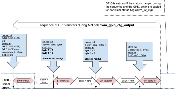
Example polling leaps_gpio_cfg_output
Using interrupt (GPIO) when command is issued from the master
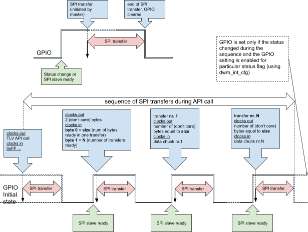
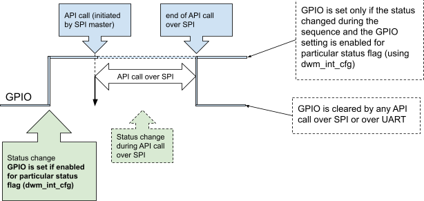
Using CORE_INT GPIO pin to notify master about the status change
This interrupt is postponed if it happens during the TLV Request response procedure described above.
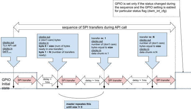
Example interrupt leaps_bh_xfer
The maximum payload size of a single TLV frame is 253 bytes (Max TLV frame supported by the slave - TLV header = 255 - 2 = 253). A number of bytes which the master wants to transfer to the slave (downlink) using the command leaps_bh_xfer is encoded in the argument of the command. Slave takes the number of downlink data and uplink data ready to be transferred to the master and decides the size and the number of transactions to transfer both the downlink and the uplink in the sequence of the SPI transfers.
Let’s say that the master wants to transfer 299 bytes of downlink data, and the slave has 1124 bytes of uplink data ready.
downlink bytes: 299 (at least 2 TLV frames)
uplink bytes: 1124 (at least 5 TLV frames)
The master executes the command leaps_bh_xfer with argument == 299. The slave responds with size == 255 and number of transactions == 5 (5 * 253 = 1265). Both downlink and uplink TLV data chunks are encoded using reserved TLV types that can be used to serialize the data encoded in multiple TLV frames. At most, 5 TLV frames are supported for now. TLV types 100-104 (0x64-0x68) are reserved for uplink data chunks. TLV types 110-114 (0x6E-0x72) are reserved for downlink data chunks.

Wakeup via SPI
If the module sleeps (in low-power mode), the wakeup procedure has to be executed before SPI/UART starts accepting commands. At least, 35 microsecond wide pulse has to be generated on the CS pin of the SPI or at least one byte has to be sent on the UART interface to wake up from the sleep (only in low-power mode).