API Operation
GPIO notification for status change
Rather than the host device initiating the SPI/UART communication, the DWM module can send notifications of status changes by toggling the dedicated GPIO pin (P0.26) to the HIGH level, as illustrated below. To enable this feature, the host device needs to use the dwm_int_cfg_set command. On detecting the HIGH level, the host device can initiate a dwm_status_get command to get the status from the DWM1001 device. Both dwm_int_cfg and dwm_status_get commands can be sent through SPI or UART schemes introduced in the previous sections.
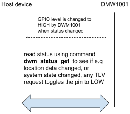
DWM1001 notifies the host device of status changes, using a data ready GPIO pin
This GPIO pin level change will be postponed if the status change happens during the SPI TLV Request/response procedure described above to avoid conflict. In detail, when the SPI is in status: “SPI: Wait for call_back”, “SPI: Wait for Read SIZE”, and “SPI: Wait for Read DATA/ERR”, the GPIO scheme will surrender the control of the GPIO pin. After the SPI communication, when the SPI is in the status “SPI: Idle”, the GPIO scheme will regain control of the GPIO pin.
API for on-module C code user application
Users can add their code and make use of the C code API functions in certain entry files provided in the onboard pack of pre-build firmware. In this way, users can add their own functions inside the module firmware and may not need to add an external host controller device.
Here are a few points the C code users should note when using the onboard firmware:
User application is based on eCos RTOS and DWM libraries.
Files used for linking with the user applications:
dwm.h - header file - wrapper for all header files necessary for building the user application
libdwm.a - static library
extras.o, vectors.o, libtarget.a - eCos static library
target_s132_fw1.ld - linker script for firmware section 1
target_s132_fw2.ld - linker script for firmware section 2
The API provides functions and defines to the user application
Common functions on operating systems like thread creation, memory allocation, access to interfaces (e.g. GPIO, SPI, ..), and synchronization (mutex, signal).
Initialization, configuration, and maintenance of the DWM communication stack
Register of callbacks for incoming data and measurements.
The API will protect for the user application against incorrect settings that could influence system performance.
System specifications
Maximum user threads: 5
RAM for the end user: cca TBD kB (TBD after D12, expected > 5KB)
FLASH for the end user: cca TBD kB (TBD after D12, expected >= 40KB)
DWM1001 threads
In the DWM1001 firmware system, there are many threads, including SPI, BLE, UART, Generic API, User App and other threads. Each thread deals with specific tasks. The SPI, BLE, and UART threads control the data transmission with external devices. They don’t parse the requests they’ve received. All received requests are sent to the Generic API thread. The Generic API thread is a parser of the received requests. It judges whether the incoming request is valid. If valid, the firmware goes on to prepare the corresponding data as a response; if invalid, the firmware uses an error message as a response. Then, the Generic API thread runs the call_back() function, which sends the prepared response message back to the thread where the request comes from. The onboard user application thread is an independent thread for the users to add their own functionalities. The entrance is provided in the dwm\examples\ folder in the DWM1001 onboard package. An example project is given in dwmexamplesdwm-simplefolder.
Position Representation
In presenting locations and distances in a Real-Time Positioning System, there are two things to consider:
Accuracy
Precision
Accuracy is the error between the position reported by the nodes and the real position. Currently, the DW1000 used in this design provides approximately 10 cm accuracy. Precision is the value a least-significant bit (LSB) represents. In the onboard firmware of this system, the precision is 1 mm, i.e. 0.001 meter. The positions are presented in 3-dimensional coordinates (X, Y, Z), where X, Y, and Z are a 32-bit integer (4 bytes). Each LSB represents 1 mm. This is for easier interpretation of the value and easier mathematics over the reported values.
When deciding the precision, it is important to choose it with respect to accuracy to get a meaningful result. It is useless to show the user precise values if accuracy is low. The 1mm precision is too fine-grained with respect to the current 10 cm accuracy. Therefore, in presenting the location, a precision of 1 cm, i.e. 0.01 meter, is used. The updated value will be presented only when the coordinate/distance has changed over 1 cm. It is similar to rounding float/double values to a meaningful number of decimal places.