UART Interface
Users can use an external host device to connect to the DWM module through UART interface at a baud rate 115200. The figure below shows the workflow of the DWM1001 UART interface. In the UART Generic mode communication, the host device is acting as the initiator, while the DWM module is the responder. DWM1001 UART provides two modes: the UART Generic mode and the UART Shell mode. The default mode of the DWM1001 UART is Generic mode. However, the two modes are transferable.
Generic mode to Shell mode: press “Enter” twice or input two bytes [0x0D, 0x0D] within one second.
If the module is in a “sleep” state in low-power mode as introduced in low-power mode wake-up mechanism, an extra byte will be needed before the double “Enter”. For example, pressing“Enter” three times will wake the module and transfer it to Shell mode. Shell mode to Generic mode: users need to input the “quit” command.
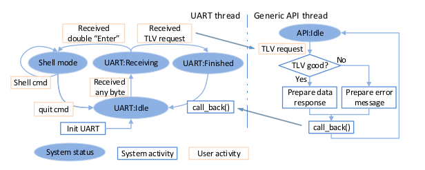
UART workflow
UART TLV Mode
UART TLV mode uses TLV format data. In this mode, the host device and the DWM module communicate using TLV Requests/responses. A full TLV Request communication flow includes the following steps:
The host device sends TLV Request;
DWM1001 responds with TLV data.
On receiving any data, the UART starts a delay timer for the following data. If new data comes in within a delay period, specifically 25 clock cycles (25/32768 second ≈ 763 μs), the UART starts the delay timer and waits for new data. The delay timer will expire if no new data comes in within the delay period. The UART then sends the received data to the Generic API thread and waits for it to return the response data or error message.
The DWM1001 UART TLV mode thread transfers between three states in serial: “UART: Idle”, “UART: Receiving”, and “UART: Finished”. Each state will transfer to its next corresponding state on certain events.
UART: Idle: is the state after initialization and after each successful TLV response. In this state, the UART only expects one byte as the start of the TLV Request or the double “Enter” command.
Waiting for an event: receiving TLV Requests.
Action on an event:
Start the delay timer.
Transfer to UART: Receiving.
UART: Receiving: is the state waiting for the end of the incoming request. On receiving any data in this state, the UART will refresh the delay timer. If the host device has finished sending bytes, the delay timer will expire.
Waiting for an event: delay period timed out.
Action on an event - if received request is double “Enter”:
Transfer to the UART Shell mode.
Action on an event - if received request is not double “Enter”:
Send received request to the Generic API thread.
Transfer to UART: Finished.
UART: Finished: is the state waiting for the Generic API thread to parse the incoming request and send the response data or error message back to the UART thread.
Waiting for event: call_back() function called by the Generic API thread.
Action on an event:
Send the response data or error message to the host device.
Transfer to UART: Idle.
UART TLV mode communication
The UART communication in TLV mode is illustrated in the figure below:
The host device sends a request in TLV format;
The DWM module responds with a message in TLV format.
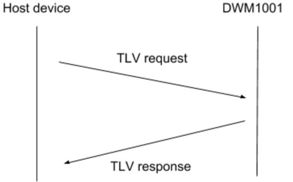
UART TLV communication
UART TLV mode communication example
The figure below illustrates an example of the host device sending the dwm_gpio_cfg_output command to set pin 13 level HIGH ([0x28, 0x02, 0x0D, 0x01] in byte array and receiving the response from the DWM module using the UART API in TLV mode. The steps of the communication flow are:
The host device sends the dwm_gpio_cfg_output command in TLV format: Type = 0x28, Length = 0x02, Value = 0x0D 0x01.
The DWM module responds in TLV format: Type = 0x40, Length = 0x01, value = 0x00,
Where Type = 0x40 indicates this is a return message, Length = 0x01 indicates that there is one byte following as data, and value = 0x00 indicates the TLV Request is parsed correctly.
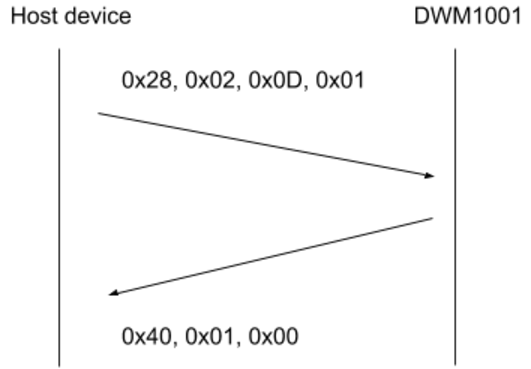
UART TLV communication example
UART Shell mode communication
UART Shell mode provides a prompt and uses Shell commands. The UART Shell mode intends to provide users with human-readable access to the APIs. Thus, all Shell commands are strings of letters followed by a character return, i.e. “Enter”. Users can input the string directly through the keyboard and press “Enter” to send the Shell commands. DWM1001 UART stays in the Shell mode after each Shell command except for the “quit” command.
As illustrated in the figure below, a full Shell command communication flow includes the following steps:
The host device sends the Shell command + “Enter” to the DWM1001.
If there’s any message to respond, the DWM1001 sends the message to the host device.
If there’s nothing to respond, the DWM1001 doesn’t send anything and keeps quiet.
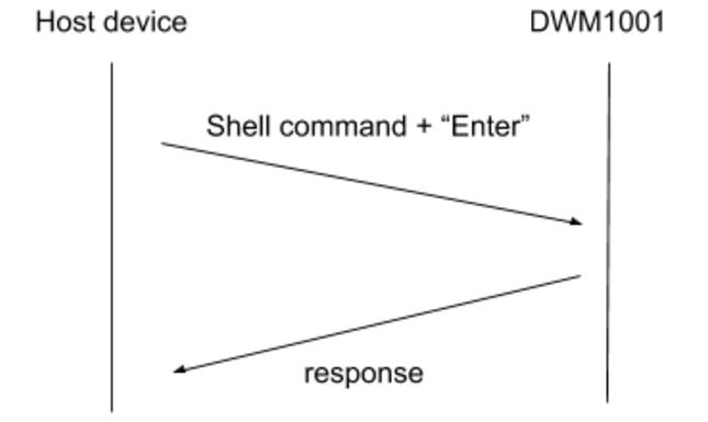
UART Shell mode communication
UART Shell Mode communication example
The figure below illustrates an example of a host device sending the “GPIO set” command using UART Shell to set pin 13 level HIGH (“gs 13” in a byte array, followed by “Enter” key, detailed in gs). The steps of the communication flow are:
The host device sends the “GPIO set” command in Shell mode: “gs 13” + “Enter”.
The DWM1001 responds to the host with the string “gpio13: 1”.
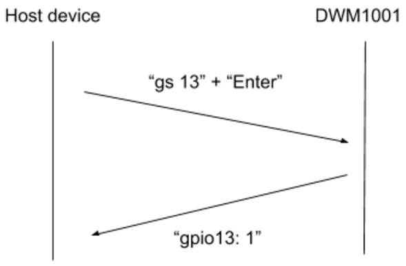
UART Shell mode communication example
low-power mode wake-up mechanism
As provided in the PANS library, the DWM module can work in a low-power mode. In the low-power mode, the module puts the API-related threads into a “sleep” state when host devices do not communicate the API . In this case, the host device needs to wake the module through external interfaces before the real communication can start.
For the UART interface, the host device needs to send a single byte first to wake up the module.
After the API transmission has finished, the host device needs to put the module back to “sleep” state to save power, as introduced in dwm_sleep and shell command quit.
UART wakeup
If DWM sleeps (in low-power mode), the wakeup procedure has to be executed before SPI/UART starts accepting commands. At least one byte has to be sent on the UART interface to wake up from sleep (only in low-power mode).