PANS PRO Demo
Prepare for setup
PANS PRO Manager application installed on an Android device.
LEAPS Center application installed on the PC.
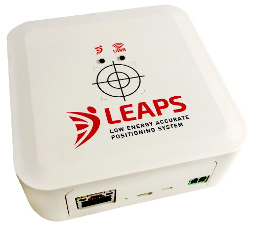
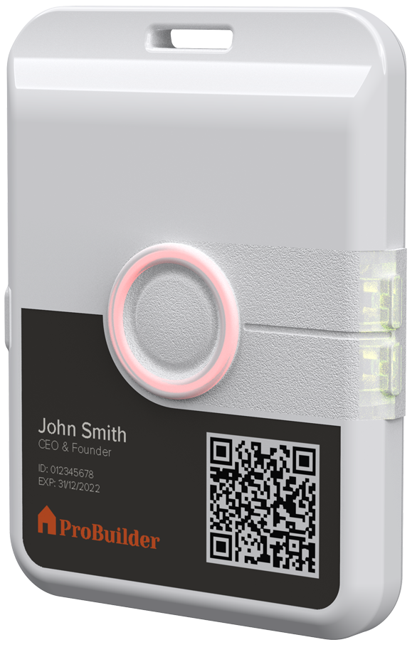
At least four LC4 devices (Anchor Node) and one LC8 device (Tag Node).
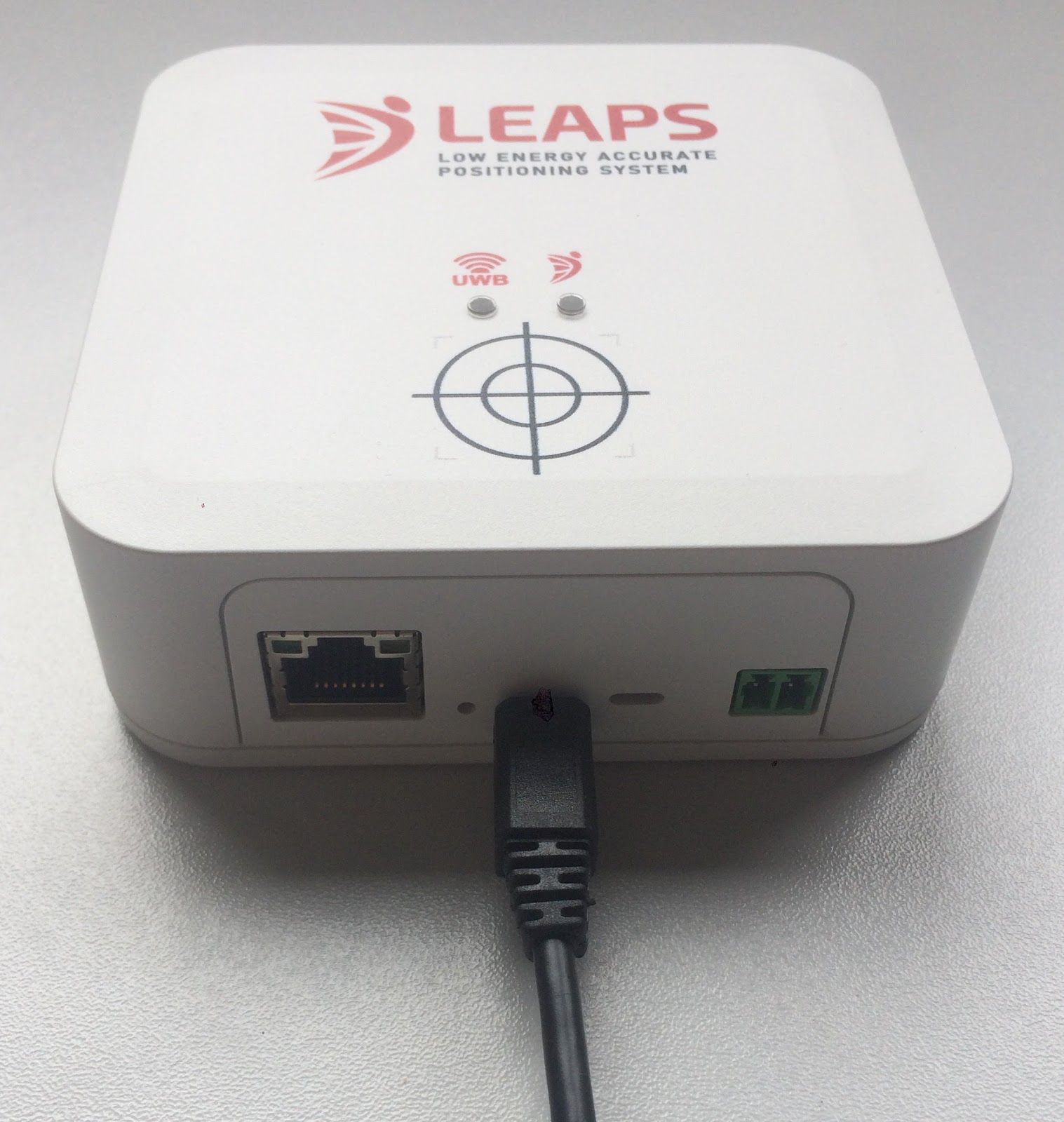
One LC5 device (Gateway Node).
Batteries or Micro USB cables for powering the devices.
Recommended: clamp or tripod with a camera mount for attachment of the Anchor devices.
Recommended: A Raspberry Pi 3B or newer version or a PC, the data server, and the web application installation.
Optional: Putty, Teraterm, minicom, or your favorite terminal application installed on your computer.
Setup time: less than 5 minutes
Overview
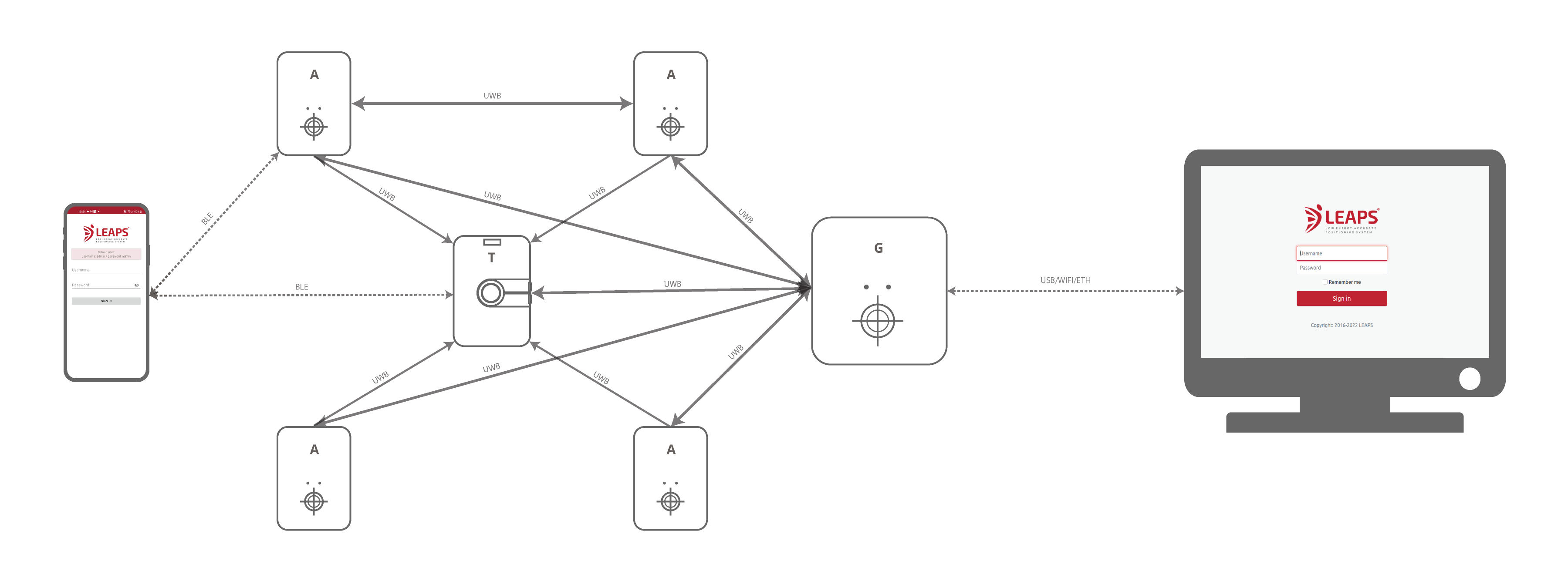
This setup demonstrates real-time navigation, tracking, and both ways of data telemetry using Two Way Ranging (TWR) technology.
Typical applications: Indoor navigation, asset tracking, and real-time data telemetry supporting uplink and downlink.
Setup instructions
Power ON the devices with already flashed the latest firmware.
The statically mounted devices will function as Anchors, providing location information to the Tags.
The moving devices will function as Tags configured in Two-Way Ranging measurement mode.
Please refer the detail guideline from the PANS PRO Manager section. Here are quick steps.
2.1. Log in using the username
adminand the passwordadmin.2.2. Once logged in successfully, click on the
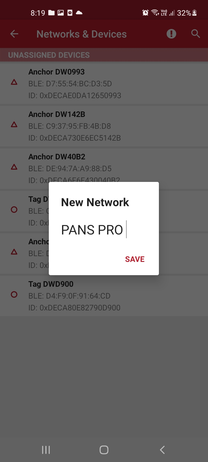
Start Device Discoveryfunction on the homepage.2.3. Assign the discovered devices to the network. Enter a network name to continue and assign all devices to this network.
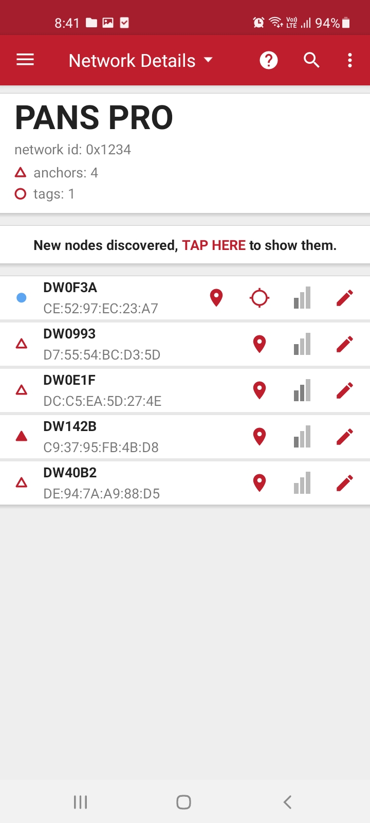
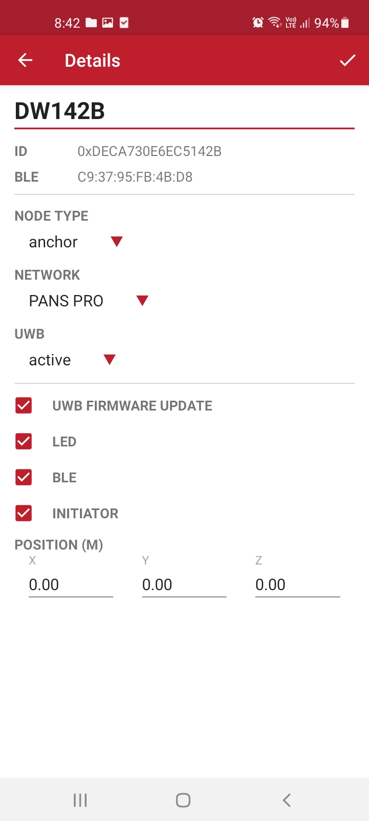
2.4. Configure one of the discovered devices as the Initiator Anchor Node (ANI) and enable Initiator Mode.
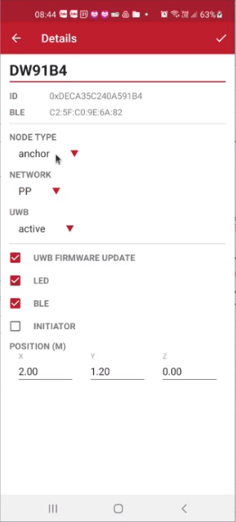
2.5. Configure three of the discovered devices as Anchor Nodes (AN) without enabling Initiator Mode.
2.6. With four Anchor Nodes (AN), you can configure the Position manually.
Check out the Auto-Positioning feature for easy anchor placement in PANS PRO Manager.
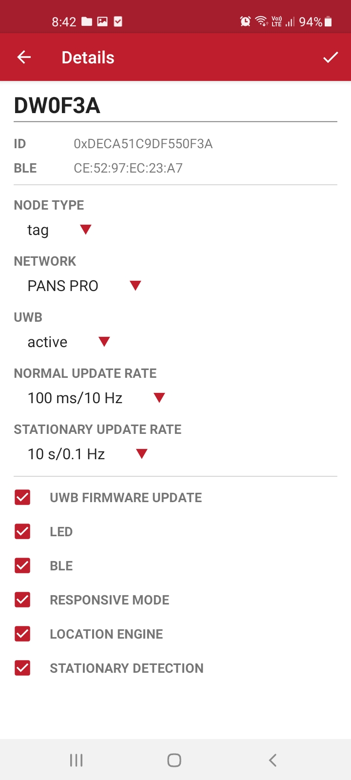
2.7. Configure one device as a Tag Node (TN) with the default
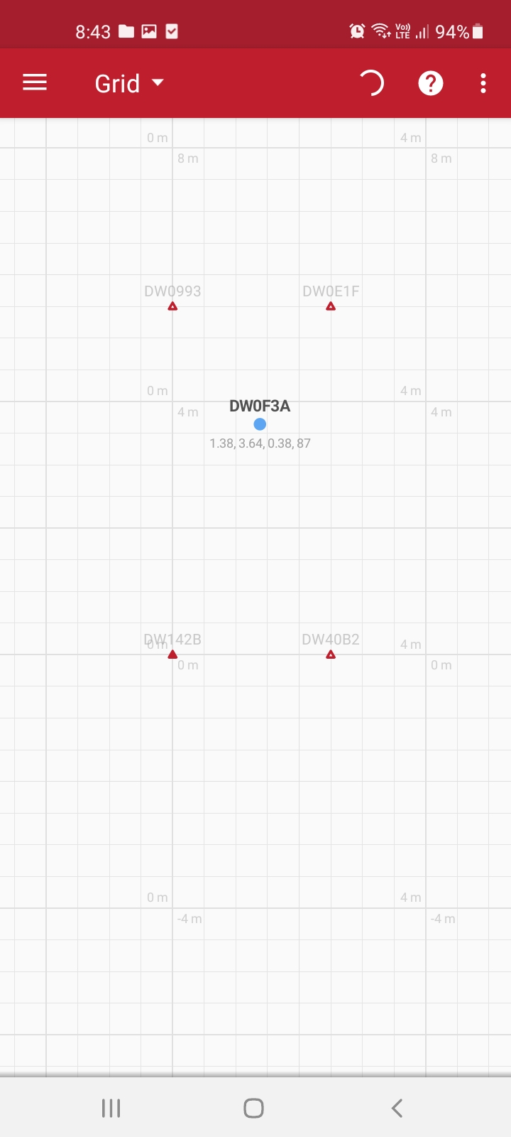
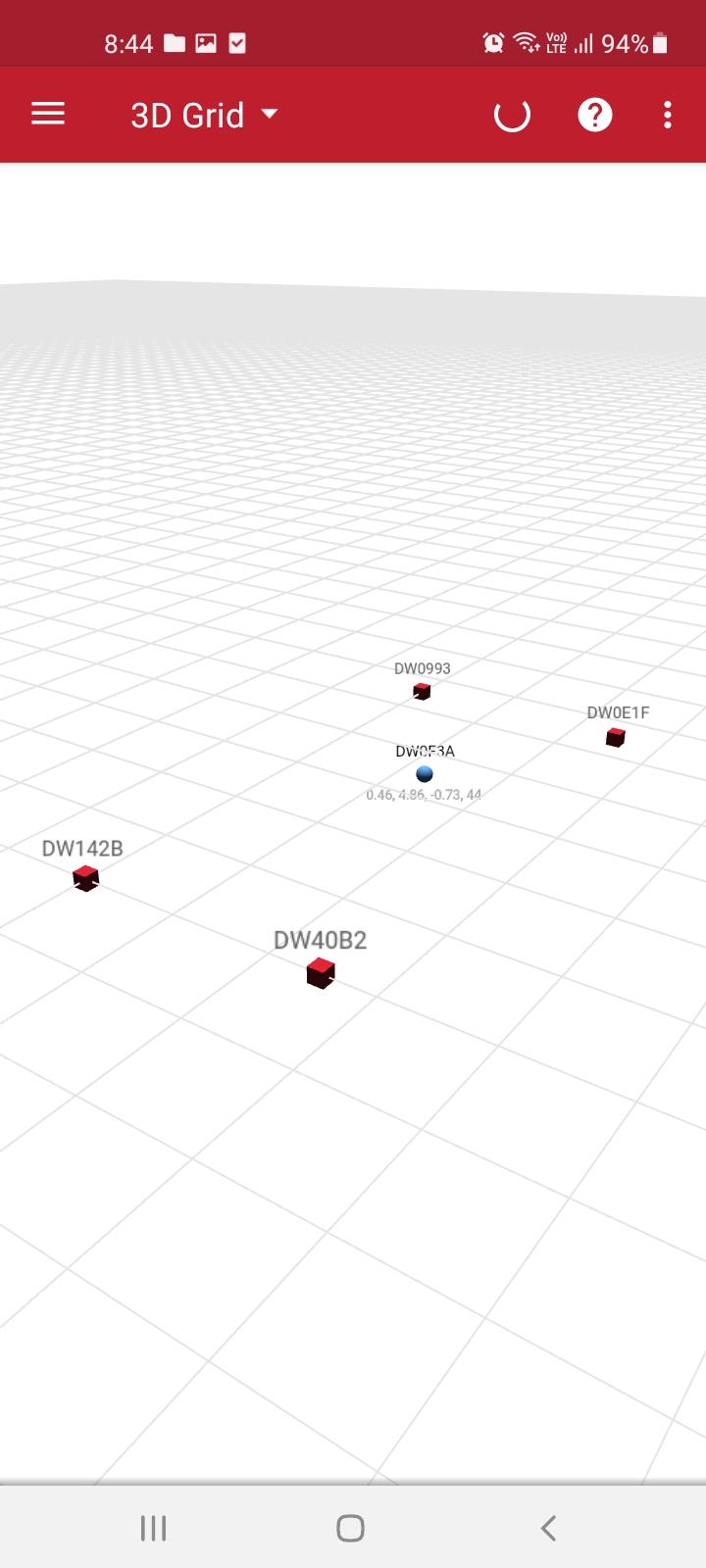
NORMAL UPDATE RATEandSTATIONARY UPDATE RATE.2.8. After completing the discovery and configuration, the network visualization can be displayed in 2D Grid or 3D Grid on the PANS PRO Manager application.
Overview
On this section, the guideline will guide how to set up the PANS PRO RTLS network to display on the LEAPS Center. In order to successfully set up the PANS PRO RLTS network, please ensure the essential hardware and software.
Instructions:
Prepare the Network:
Use the configuration via
PANS PRO Manageas described in theQuick Start with Phonetab to configure the network.
Set up the Gateway Board: Use either
PANS PRO DockerorPANS PRO Raspberry Pi.Note: Flash the latest firmware if it’s not already available on the board.
Gateway Configuration
Configuration can be done by connecting the device via USB and using an on-board shell command.Press double Enter to enable the shell command mode.2.1. UWB Networking Configuration
Configure network ID
leaps> nis
usage: nis PANID
Configure device to become a Gateway
leaps> nmb
ok
or
leaps> acs leds 1 uwb 2
ok
2.2. Device IP Address Configuration
Default is DHCP (dynamic IP address) so no need to configure unless needed.
Usage
leaps> ipv4
usage: ipv4 [static|dynamic] [addr STRING] [mask STRING] [gw STRING]
Note
The device will be reset upon a successful configuration.
Static IP address configuration
leaps> ipv4 addr 192.168.1.100 static
ipv4 ok(0)
Network mask configuration
leaps> ipv4 mask 255.255.255.0
ipv4 ok(0)
Enabling static IP address which has been configured previously
leaps> ipv4 static
ipv4 ok(0)
Enabling DHCP
leaps> ipv4 dynamic
ipv4 ok(0)
Configuring all in one step
leaps> ipv4 addr 192.168.1.100 mask 255.255.255.0 static ipv4 ok(0)
2.3. Configuring LEAPS Server connection
Usage
leaps> peer
usage: peer [addr STRING] [port NUM] [tls 0|1]
Note
The device will be reset upon a successful configuration.
Configuring connection with the LEAPS Server at IP address 192.168.200.1 and on port 7777
leaps> peer addr 192.168.200.1 port 7777 tls 0
peer ok(0)
Disable TLS
leaps> peer tls 0
peer ok(0)
Enable TLS
leaps> peer tls 1
peer ok(0)
Combined configuration of LEAS Server host and TLS
leaps> peer host example.com tls 1
peer ok(0)
Correct status of the system when TLS is disabled
leaps> si
[000081.971 INF] sys: fw1 fw_ver=x01030000 cfg_ver=x00030000
[000081.976 INF] inet: up tls=off addr=192.168.1.100 mask=255.255.255.0 gw=192.168.200.1 (dynamic)
[000081.983 INF] inet: peer=192.168.200.1:7777 (-)
[000081.987 INF] uwb: panid=x0000 addr=xDECA84B1B8544434
[000081.992 INF] uwbmac: connected
[000081.997 INF] mode: bn (act)
[000082.000 INF] cfg: enc=0 ble=1 leds=1 fwup=0 label=ID4434
[000082.005 INF] enc: off (nokey)
[000082.008 INF] bdg: connected
Correct status of the system when TLS is enabled
leaps> si
[000027.316 INF] sys: fw1 fw_ver=x01030000 cfg_ver=x00030000
[000027.321 INF] inet: up tls=on addr=192.168.1.100 mask=255.255.255.0 gw=192.168.200.1 (dynamic)
[000027.328 INF] inet: peer=123.123.123.123:7777(server.example.com)
[000027.332 INF] uwb: panid=x0000 addr=xDECA84B1B8544434
[000027.337 INF] uwbmac: connected
[000027.342 INF] mode: bn (act)
[000027.345 INF] cfg: enc=0 ble=1 leds=1 fwup=0 label=ID4434
[000027.350 INF] enc: off (nokey)
[000027.353 INF] bdg: connected
Open LEAPS Center
Launch it via
PANS PRO DockerorPANS PRO Raspberry Pi.
Log In
Use the username
adminand passwordadmin.

Select Networks
Click on
Networksin the left navigation menu.
Add New Network
Provide a Name and ID.
Select Protocol Type as PANS.
Enter the Host and TCP Port.
Fill in the Username, Password, and Topic Prefix.
Test the Connection
Press the
Testbutton to check the connection, then pressSaveto create the network.
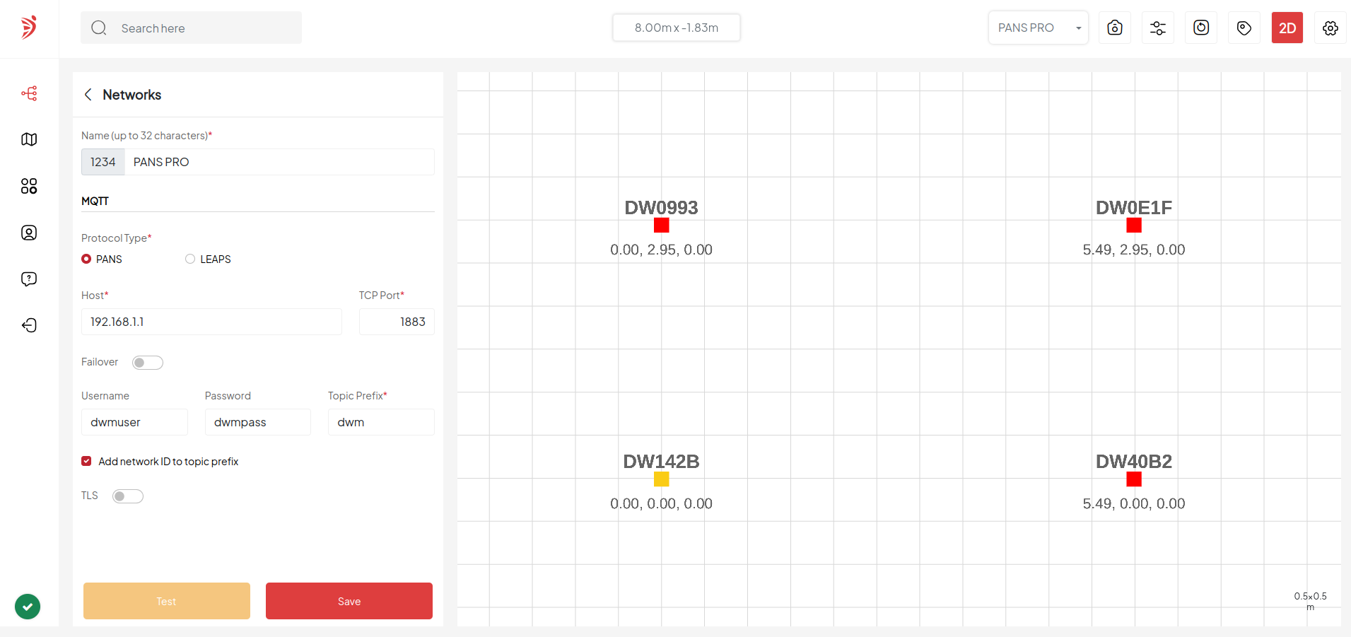
Once finished, the network visualization will be displayed in both 2D gird and 3D gird views in the application. For more information, see the
LEAPS Centerconfiguration and usage.
Reference to PANS PRO API.
When Bluetooth Low Energy (BLE) and the LED are both off, users may erroneously perceive the board as non-functional. In this scenario, the only recourse for the user is to initiate a Factory Reset (frst) command.
Please check the version. We recommend you use the latest official version.
Note
Refer to the software infrastructure to further explore the power of this demo. Our support includes PANS PRO Docker and PANS PRO Raspberry Pi.
For any comments or questions about our products, we encourage you to visit our LEAPS Forum.
