Hardware Interfaces
Before proceeding with the demos, it is essential to get familiar with the hardware interface, particularly focusing on the buttons A, B, and C, the 2 USB-C ports, the front RGB LEDs and the two side GREEN LEDs. Understanding these elements will significantly help you in setting up each demonstration effectively.

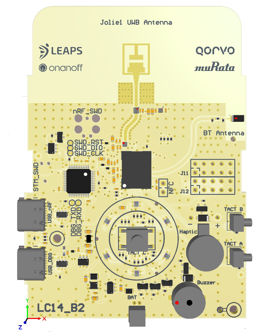
- Buttons, LEDs and user interaction
Button A: Power ON/OFF button (long-press).
GREEN LED: Power status
Button B: Switch between Qorvo NI / UCI and LEAPS UWBS modes (long-press).
GREEN LED: UWB status
Button C: N/A (for future use).
RGB LEDs: indicates device mode during the power on.
RED is LEAPS UWBS
BLUE is Qorvo NI
GREEN is Qorvo UCI
A buzzer: used for alarm.
A haptic motor: used for alarm.

- Data interfaces
USB-C Data Port 1: USB command line and binary API.
USB-C Data Port 2: DAPLink + USB/UART command line and binary API.
Integrated UWB antenna.
Integrated Bluetooth antenna.
- Development interfaces
Integrated DAPLink with SWD Debugger and USB/UART converter: used for programming, debugging purposes and for device configuration.
6-pin Tag Connect compatible connector for external J-Link debugger.
PCB jumper pads: SWD_RST, SWD_DIO, SWD_CLK, DBG_TXD, DBG_RXD.
GPIOs: J11 (P0.21, P0.24, DW_GP0, DW_GP1, DW_GP2, DW_GP3, DW_GP4, DW_GP5, DW_GP6), J12 (P0.11, P0.12, P0.13, P0.14, P0.29, P0.31, P1.14, P1.07).
NFC antenna pads: P0.09/NFC1, P0.10/NFC2.
3.7V battery connector.